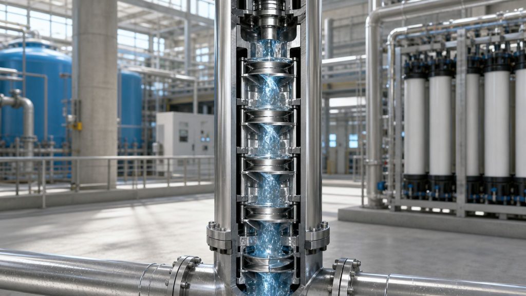
You're usually looking at a vertical turbine pump when the process problem is already defined by the source water. The plant needs stable flow. The treatment skid is specified. The RO vendor has set feed conditions. The filtration package is sized. Then someone realizes the water is sitting in a deep well, a wet pit with large level swings, or an intake structure that punishes a standard horizontal pump.
That's when pump selection stops being a catalog exercise and becomes a system decision. In industrial water service, a vertical turbine pump isn't just a way to move water uphill. It's often the mechanical link between raw water variability and downstream equipment that hates variability, especially cartridge filters, multimedia filters, RO membranes, and other industrial treatment assets.
Table of Contents
- When to Choose a Vertical Turbine Pump
- Core Components and Operating Principle
- Sizing Your Pump with Performance Curves
- Material Selection for Industrial Water and Filtration
- Installation Piping and NPSH Considerations
- Common Failure Modes and Preventative Maintenance
- Integrating VTPs with Your Filtration and RO Systems
When to Choose a Vertical Turbine Pump
A common plant scenario goes like this. The project team has a new industrial RO system on order, the feed tank is not an option because the raw water comes directly from a deep well, and the process still needs dependable flow into pretreatment. A standard end-suction pump can't solve the suction condition because it isn't built to lift from that kind of depth. A vertical turbine pump is.
That's why these pumps show up so often in industrial water work. They're the right answer when the water source sits well below grade, when the intake structure has limited footprint, or when the process needs high flow and meaningful head from a below-surface source. Deep wells, river intake structures feeding clarification and filtration, cooling water basins, and large finished-water transfer systems are typical examples.
The market scale reflects how established that role has become. The global vertical turbine pump market was valued at USD 25.79 billion in 2024 and is projected to reach USD 34.87 billion by 2030, growing at a CAGR of 5.16%, according to global vertical turbine pump market analysis from GII Research.
Where they earn their keep
In industrial water treatment, the selection usually makes sense when the system has these traits:
- Deep source water: Wells, caissons, or intake cans where the hydraulic section needs to sit below the water surface.
- Large flow with stable discharge: Feed to pretreatment trains, cooling systems, service water headers, or high-volume backwash systems.
- Limited floor space: The vertical arrangement helps when the plant can't spare long horizontal suction piping runs.
- Maintenance access requirements: The driver stays above ground, which matters in facilities that don't want an underwater motor.
Practical rule: If the source water level drives the pump arrangement more than the discharge piping does, start by evaluating a vertical turbine pump.
These pumps are not universal answers. If the liquid is dirty enough to threaten close running fits, or if the process benefits from a packaged skid pump with simple pull-out maintenance, another design may be easier to live with. But when the problem is high-head water withdrawal from below grade, this is usually the pump you evaluate first.
Core Components and Operating Principle
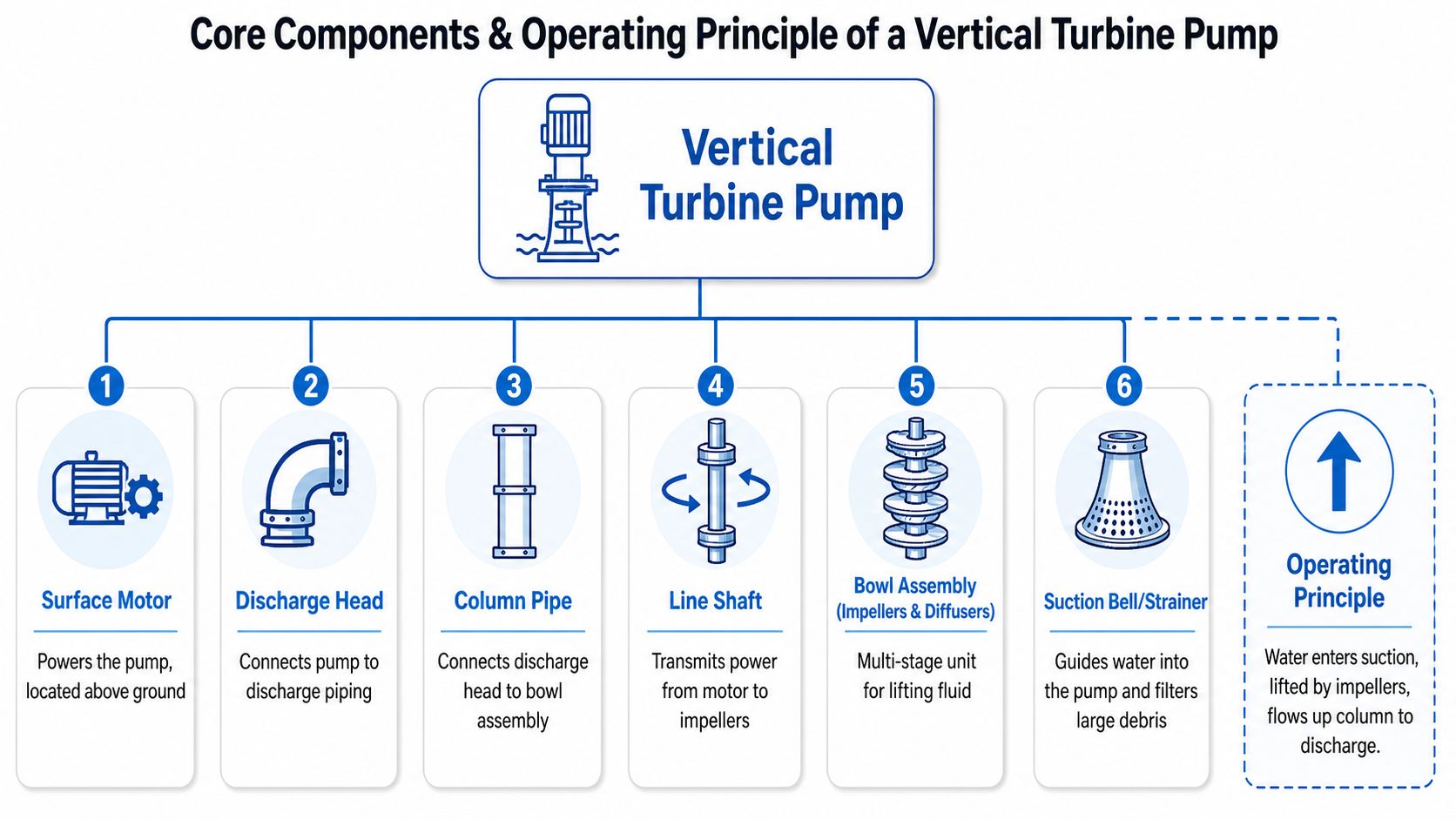
The easiest way to understand a vertical turbine pump is to read it from top to bottom. The motor stays on the surface. The hydraulic work happens below the liquid level. Everything in between exists to transmit torque, support the rotating assembly, and carry flow back up to discharge.
What sits above grade
At the top is the driver, usually an electric motor in industrial water service, though engines are used in some remote or special-duty applications. Below that is the discharge head, which supports the pump assembly and turns the upward flow into the plant's discharge piping.
Then comes the column pipe. This isn't just a structural extension. It carries the pumped water upward while housing the line shaft, which transmits power from the surface motor down to the submerged bowl assembly. Along that shaft are bearings that keep the rotating parts aligned over the full suspended length.
Unlike a submersible design, the motor isn't sitting in the water. That's one reason many plants prefer this arrangement for maintainability. You can service the driver without pulling an entire underwater motor assembly.
What does the hydraulic work
At the bottom is the bowl assembly, which contains the impellers and diffusers. Within this assembly, the pump builds head. Each stage adds pressure, then hands the flow to the next stage. The simplest analogy is stacked batteries. One battery gives you a set voltage. Stack more in series and the total increases. Pump stages work the same way with head.
Industrial deep-well vertical turbine pumps are built specifically around that principle. Each stage typically adds 50 to 150 feet of head, enabling total dynamic heads exceeding 2,000 feet in high-pressure process water systems, as described by National Pump Company's deep-well vertical turbine pump product information.
A few component relationships matter during selection:
| Component | Why it matters in practice |
|---|---|
| Motor | Must handle the pump's thrust and operating load, not just nameplate horsepower. |
| Discharge head | Affects piping layout, support, and maintenance access. |
| Column and shaft | Long assemblies increase alignment sensitivity and bearing importance. |
| Bowl stages | Determine how much head the pump can develop. |
| Suction bell or strainer | Sets the first line of defense against large debris entering the hydraulics. |
Water enters through the suction bell, passes through the first impeller, gains velocity, then moves through a diffuser where that velocity is converted into pressure. The flow repeats that sequence stage after stage, then rises through the column to the discharge head.
The modular design is what makes a vertical turbine pump adaptable. You can change stage count, bowl geometry, shafting, and materials without changing the basic architecture.
That flexibility is useful in industrial treatment plants because feed conditions don't stay static. Water levels move. Pretreatment pressure loss changes as filters load. Process expansions raise flow requirements. A pump with modular staging gives the engineer room to solve those shifts intelligently.
Sizing Your Pump with Performance Curves
A vertical turbine pump is easy to underspecify when the team focuses only on rated flow and discharge pressure. That usually looks fine on paper and performs badly in the field. Good sizing starts with the curve, but it doesn't end there.
Read the curve like an operator, not a brochure
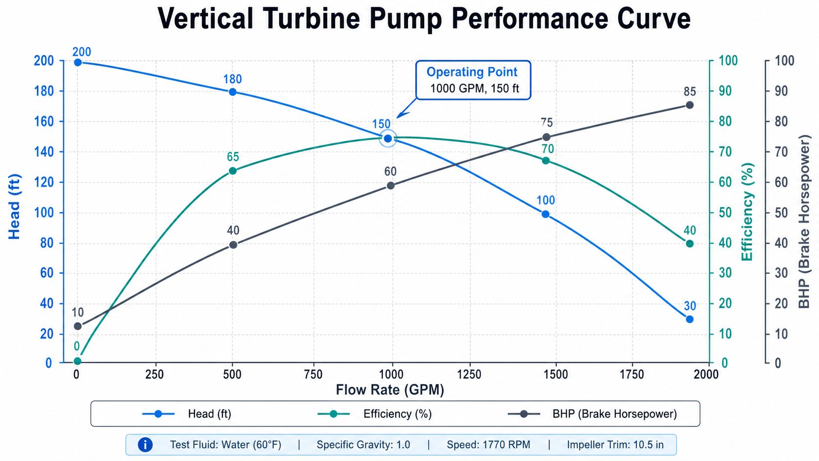
On a typical performance curve, you're looking at four linked behaviors. Flow changes head. Head changes power. Efficiency rises and falls across the operating range. NPSH required also shifts with flow, even if the curve presentation varies by manufacturer.
For industrial water systems, the most useful question is not “Can this pump hit design flow?” The better question is “Where will it spend its life?” If the plant runs near one operating point most of the time, that point should land in a stable part of the curve, not at the ragged edge where efficiency drops and thrust behavior gets less forgiving.
Use the curve to pressure-test these decisions:
- Set the actual duty point: Include static lift, discharge pressure requirement, pretreatment losses, membrane feed constraints, and seasonal water level effects.
- Check stage selection: A bowl set can meet flow and still be wrong if the stage count doesn't match actual developed head.
- Review power draw: Motor margin matters, especially if the process water quality can shift operating conditions.
- Look beyond the design point: Startup, low-level operation, and partially loaded filter trains can move the pump away from the preferred region.
The head you don't see on the factory curve
Many specifications frequently go wrong. Operators often compare field readings to factory curves as if the installed pump sees the same hydraulic conditions represented in the test data. It doesn't. Deep-well service adds a hidden penalty through column friction loss.
According to Franklin Electric's discussion of column friction loss in deep-well turbine pumps, operators often fail to isolate well-specific column friction loss, and that loss can be up to 15 to 20% of total head loss in 100-foot columns. It can't be measured directly in the field, which is exactly why it gets missed.
That matters more than most new engineers expect.
If the design team ignores that hidden head loss, they may select too few stages or underestimate horsepower. The pump then operates away from its intended condition. Wear shows up first in the rotating assembly and bowl package, but the larger system pays too. Filtration feed becomes less stable. Control valves compensate. RO pretreatment sees more fluctuation than it was designed for.
Factory curves tell you what the pump can do. They do not tell you what your well, column, and intake geometry will take away.
A practical sizing review should include this short check:
- Water level range: Don't size only at nominal level. Include worst credible drawdown or sump swing.
- Column loss review: Use the manufacturer's engineering method for the installed column geometry.
- Pretreatment losses: Dirty cartridge housings, loaded media beds, and fouling control devices add real head.
- Control philosophy: A fixed-speed pump feeding a variable treatment train behaves differently from a controlled system with downstream pressure management.
If the process includes filters upstream of RO, write those losses into the duty case as they will exist in operation, not as they appear on a clean datasheet. Engineers often treat the pump and the water treatment skid as separate packages. In practice, they are one hydraulic system.
Material Selection for Industrial Water and Filtration
Material selection is where many industrial water projects determine whether the pump will be routine equipment or a recurring maintenance problem. The correct material set depends on what the water does chemically and physically. Cost still matters, but bad metallurgy is one of the fastest ways to turn a decent hydraulic design into a poor asset.
Match metallurgy to the water, not the budget sheet
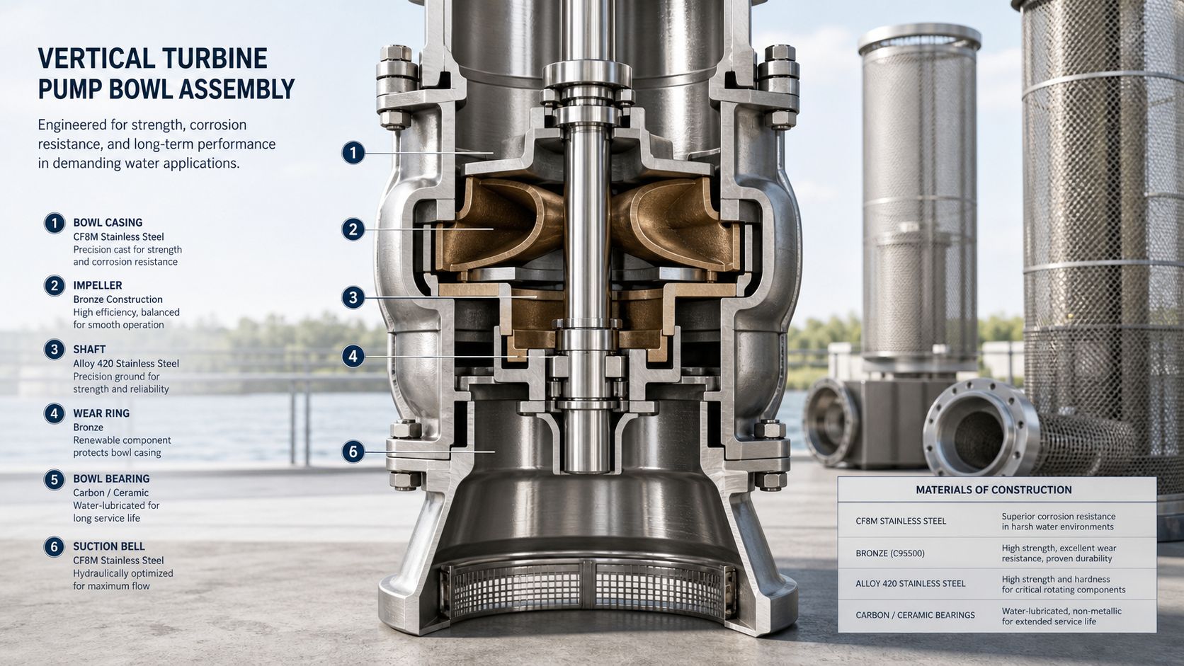
For relatively mild utility water, cast iron or ductile iron may be acceptable in many pump components. Plants use those materials successfully in cooling tower makeup, service water, and other duties where corrosion risk is manageable and solids loading is controlled.
That logic breaks down quickly in aggressive water. Brackish RO feed, chloride-bearing groundwater, mining water, and process streams with unpredictable chemistry can punish standard materials. In those cases, stainless construction for bowls and wetted internals is often the safer decision. The exact grade still has to follow the chemistry. Treating all “stainless” as interchangeable is a specification mistake.
A simple selection framework helps:
| Water condition | Better material direction |
|---|---|
| General utility water | Cast iron or ductile iron may be workable if corrosion risk is low |
| Brackish or chloride-bearing water | Stainless wetted parts are often the right starting point |
| Corrosive process water | Review higher alloy options and shaft, fastener, and bearing compatibility together |
| Solids-laden intake water | Focus on wear resistance, bearing materials, and internal clearances |
If the pump feeds multimedia filters, cartridge housings, or RO skids, upstream corrosion products and wear particles don't stay “just a pump problem.” They become a fouling problem for the rest of the plant. That's why pump metallurgy should be reviewed alongside pretreatment hardware like industrial cartridge filter housings, not in isolation.
Solids change the bearing conversation fast
High-solids service is where generic pump guidance often falls short. Many maintenance documents assume relatively clean water. Industrial water sources don't always cooperate. River intake water, mine water, recycled process water, and some oil and gas utility streams can carry suspended solids and turbidity that shorten bearing life quickly.
National Pump Company's installation and operation guidance for vertical turbine pumps notes an important nuance that often gets missed. In high-solids industrial water streams, adjusting bearing spacing from 10 feet to 5 feet and using advanced materials such as Vespel CR-6100 is critical.
That detail changes specification strategy. If you expect solids, don't just ask whether the bowl material is corrosion resistant. Ask these more useful questions:
- What supports the shaft over the full setting length? Long unsupported spans are less forgiving in dirty service.
- What bearing material is specified? Clean-water choices may not survive abrasive fines.
- How will turbidity vary over time? Intermittent dirty water can still destroy components if the design assumes consistently clean service.
- What's downstream of the pump? RO membranes and fine filtration equipment raise the cost of upstream wear debris.
A system-first material review always beats a pump-only review. Bearings, shafting, bowls, and downstream treatment equipment all feel the same water.
When engineers tie material selection to actual water chemistry and solids behavior, vertical turbine pumps become much more predictable assets. When they don't, the plant ends up troubleshooting symptoms instead of eliminating causes.
Installation Piping and NPSH Considerations
A well-selected vertical turbine pump can still fail early if the intake geometry is poor or the piping arrangement creates unstable suction conditions. In industrial water service, NPSH is where pump mechanics and civil layout collide.
NPSH problems usually start at the intake
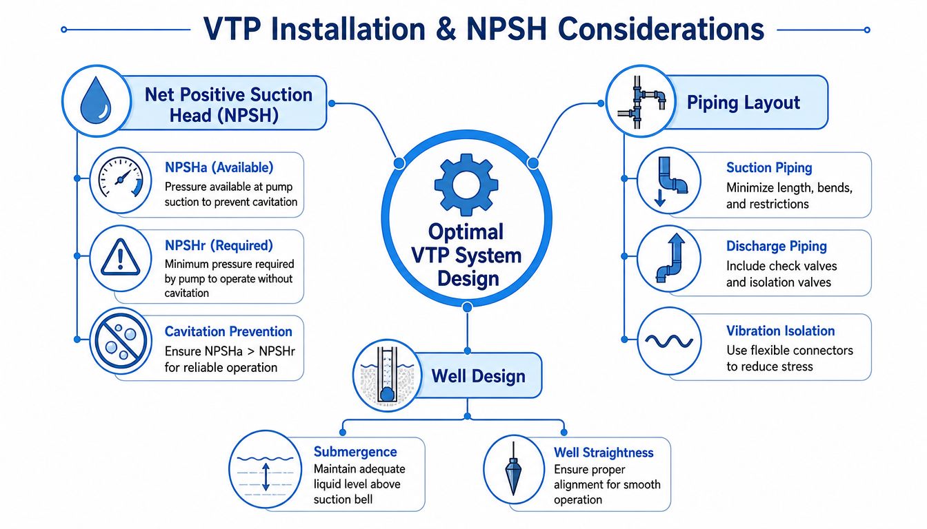
New engineers often treat NPSH as a line item from the pump curve. That's only half the story. NPSH required belongs to the pump. NPSH available belongs to the system. If the available margin collapses because the sump level drops, the intake vortices, or the suction approach flow is ugly, the pump won't care how nice the submittal looked.
For vertical turbine pumps, minimum submergence is one of the most practical design issues. The pump may not need priming in the usual sense, but it still needs enough liquid above the suction bell to avoid air-entraining vortices and unstable inflow. In variable-level sumps, this becomes a moving target.
A few installation realities matter more than theoretical neatness:
- Straight approach flow matters: Swirl and asymmetric entry conditions load the pump unevenly.
- Submergence is not a guess: Water level must stay high enough above the suction bell across operating conditions.
- Sump geometry changes behavior: Corners, narrow pits, and poor inlet placement can promote vortex formation.
- Discharge arrangement still matters: Poorly restrained piping can transmit vibration back into the pump head.
If a pump sounds like it has gravel passing through it during low-level operation, treat that as an intake design alarm, not just a pump noise complaint.
A practical installation checklist
For industrial water systems tied to filtration and RO, the installation review should be grounded in plant consequences. Cavitation damage is bad enough inside the pump. It's worse when unstable flow and entrained air upset downstream pretreatment.
Use a checklist like this during design and startup:
- Confirm the lowest operating water level. Don't use a nominal level from a process narrative if operators know the pit regularly swings lower.
- Verify submergence over the suction bell. This is especially important in backwash tanks, equalization basins, and raw water sumps with cycling level controls.
- Review intake hardware. Anti-vortex baffles, bell mouths, trash exclusion, and proper spacing are often more valuable than late-stage troubleshooting.
- Minimize avoidable piping stress. The discharge head should not become the structural correction for bad pipe alignment.
- Check for air release and transient behavior. Fast valve action and unstable level control can create operating conditions the pump never saw during factory testing.
A short comparison helps keep the concepts straight:
| Term | What it belongs to | Why you care |
|---|---|---|
| NPSHr | Pump | Minimum suction energy the pump needs to avoid cavitation |
| NPSHa | System | What the intake and liquid conditions actually provide |
| Minimum submergence | Intake design | Prevents vortices and air entrainment at the suction bell |
Plants that get this right usually treat the pump, wet well, level controls, and pretreatment feed stability as one design problem. Plants that split those scopes between vendors often inherit a startup headache.
Common Failure Modes and Preventative Maintenance
A vertical turbine pump usually tells you it's unhappy before it fails completely. The trouble is that plants often assign the symptoms to the wrong cause. They call it “pump wear” when the actual issue is low submergence, solids loading, poor alignment, or thrust outside the intended operating range.
Hydraulic failures
Cavitation is one of the most damaging hydraulic failure modes. It erodes impeller surfaces, creates noise, and drives vibration upward through the assembly. In water treatment plants, the root cause is often inadequate NPSH available during low-level operation or unstable intake flow rather than a bad pump design.
Another hydraulic problem is operating too far from the intended duty point. Flow instability can show up as inconsistent feed to filters or RO pretreatment. Operators may chase the symptom with valves or control logic, while the pump continues running in a region that increases recirculation, thrust variation, and component stress.
Watch for these indicators:
- Changing sound signature: Crackling or gravel-like noise often points to cavitation or air entrainment.
- Efficiency complaints from operations: If the plant can't maintain pressure without opening controls further, check hydraulic condition before blaming instrumentation.
- Visible performance drift: Declining flow at similar system demand usually means something in the hydraulic path has changed.
Mechanical and electrical failures
Mechanical wear often concentrates in the line shaft bearings, shafting, bowl bushings, and couplings. In dirty service, suspended solids accelerate wear dramatically. In long-setting pumps, even modest misalignment can become expensive because the rotating assembly has so much length to amplify the error.
Motor issues usually trace back to load and thrust. A pump that is staged incorrectly, operated far off its intended point, or subjected to unstable hydraulic conditions can overload the thrust bearing arrangement. Electrical symptoms then appear, but the root cause started hydraulically or mechanically.
A maintenance program should connect those dots instead of treating each symptom in isolation.
Don't wait for failure to confirm a diagnosis. Trend vibration, amperage, and operating level together. The pattern usually shows up before the damage does.
Useful preventive actions include:
- Routine vibration review: Trend changes by operating condition, not just by date. A low-level sump condition may be the trigger.
- Power draw tracking: A shift in amperage can indicate hydraulic deviation, rising mechanical drag, or both.
- Lubrication system checks: If the design uses external lubrication arrangements, verify function before startup and after outages.
- Alignment verification: Particularly after piping work, motor replacement, or head maintenance.
- Inspection after water quality events: Storm runoff, process upsets, or source-water changes often explain sudden wear patterns.
Plants that want fewer surprises should also document maintenance history against source-water conditions. That simple step often turns “random” bearing failures into a very recognizable water-quality problem. For teams building a more disciplined service routine, a structured approach to pump maintenance practices can help standardize inspections and response timing.
Integrating VTPs with Your Filtration and RO Systems
A vertical turbine pump earns its place when the treatment train depends on stable inlet conditions that a horizontal skid pump cannot reliably provide from a deep sump, wet well, or intake structure.
The integration problem is usually not pump capacity. It is how the pump behaves when the water treatment system changes state. Filters foul. Backwash valves shift. Cartridge differential pressure rises between changeouts. RO systems ramp, recycle, and trip. If the source pump was selected only for a nameplate flow and head, those normal process events show up as pressure swings at the pretreatment skid, unstable level control in break tanks, and avoidable stress on downstream equipment.
Where a vertical turbine pump fits well
A good fit is a raw water intake feeding clarification, media filtration, ultrafiltration, or RO pretreatment where the suction source is below grade and available NPSH changes with sump level. In that service, the bowl assembly stays submerged while the driver remains accessible above the floor, which solves a real plant problem. It pulls from a low source without building a long suction lift arrangement that is harder to prime and less tolerant of level variation.
Integration with filtration deserves more attention than it usually gets. A VTP upstream of automatic filters or multimedia vessels should be checked for minimum stable flow during low-demand periods, not just full production. If plant demand drops and the pump keeps running near shutoff, heat rises in the bowl assembly, recirculation increases, and pressure control gets erratic. That often shows up as filter valve hunting or repeated high differential alarms that operators blame on the skid.
RO pretreatment adds another layer. The source pump does not feed membranes directly in most plants, but it still sets the hydraulic conditions that the rest of the system has to absorb. Review pretreatment losses, tank operating levels, control valve positions, and the full piping logic shown in a reverse osmosis system installation diagram. That step helps avoid a common mistake: selecting the intake pump for clean-water conditions, then discovering that fouled pretreatment pushes the operating point into a less stable part of the curve.
One integration case that gets missed is backwash supply. A VTP can work well as a dedicated backwash water pump if the source basin level is low and the required flow arrives in short, high-rate bursts. But the pump, motor, and controls must be checked for frequent starts, thermal limits, and the transient pressure drop in the common header when multiple filters sequence close together. I have seen plants size the pump correctly for steady flow and still get poor backwash because the distribution piping was never evaluated as a system.
Where another pump type may be better
Some services favor a different design. If the water is already in a flooded indoor tank, maintenance access is tight, or solids are stringy enough to threaten line-shaft bearings and bowl clearances, a horizontal split case, end suction, or submersible arrangement may be easier to keep running.
Water quality matters here. Industrial source water headed to treatment is often chemically awkward before pretreatment does its job. Brackish water, chlorides, sulfides, low pH, polymer carryover, or abrasive fines can all change the right answer. A VTP can still be the correct machine, but only if the bowl material, shafting, bearing materials, and column configuration match the actual water, not the original design basis from a cleaner season.
Choose the pump that fits the source geometry, the control philosophy, and the way the treatment plant really operates on a bad day, not just during acceptance testing.