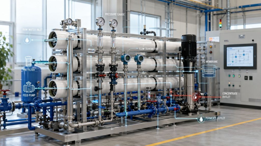
You're probably staring at a plant layout, a P&ID draft, and a procurement list that already includes membranes, vessels, pumps, and filters, while the mechanical room itself is telling a different story. Pipe rack space is tighter than expected, the feedwater quality isn't as stable as the lab sample suggested, and every decision now affects startup risk, cleaning frequency, and membrane life.
That's where most industrial RO projects either become reliable utility assets or expensive troubleshooting exercises. A generic reverse osmosis system installation diagram rarely helps once you move into real process conditions, real maintenance constraints, and real uptime expectations. Industrial systems need proper pre-treatment, workable piping geometry, accessible instrumentation, and a commissioning sequence that protects the membranes from day one.
Table of Contents
- Beyond the Blueprint An Introduction to Industrial RO Installation
- The Core Industrial RO Skid Diagram Explained
- Configuring the Essential Pre-Treatment Train
- Piping Valving and Instrumentation Layout
- Electrical Controls and System Commissioning
- Common Installation Errors and Long-Term Best Practices
Beyond the Blueprint An Introduction to Industrial RO Installation
An industrial reverse osmosis system installation diagram has to do more than show where the pump, vessels, and valves sit. It has to reflect how the system will run under fluctuating feed conditions, how technicians will service it, and how the plant will respond when quality drifts or pretreatment performance drops.
That matters in sectors like mining, food and beverage, chemical processing, and utility water production. In those environments, the RO skid isn't an isolated package. It sits inside a larger treatment train that includes solids removal, chemistry control, storage, reject handling, and downstream users that often have narrow quality tolerances.
A drawing that looks complete on paper can still fail in the field for simple reasons. The cartridge housings may be inaccessible for changeout. The antiscalant quill may be installed too close to a pump suction. The membrane vessel layout may leave no room to pull elements. A conductivity sensor may be placed where it tells the operator almost nothing useful.
Practical rule: If maintenance access, sample points, and drain routing aren't on the installation diagram, the diagram isn't finished.
Industrial buyers also need the diagram to support equipment selection. That means specifying the actual classes of components being purchased, not just generic boxes. A serious skid package often includes multimedia filtration, softening or antiscalant dosing, Fil-trek cartridge filtration, a high-pressure pump matched to the design recovery, and membrane elements from established manufacturers such as LG or Veolia.
The most durable projects are the ones where the installation drawing and the procurement package were developed together. The skid footprint, pressure class, material compatibility, valve arrangement, and instrument placement all support the membrane design basis. When that alignment is missing, teams usually end up modifying pipework after startup, and those changes are almost always more expensive than getting the layout right before fabrication.
The Core Industrial RO Skid Diagram Explained
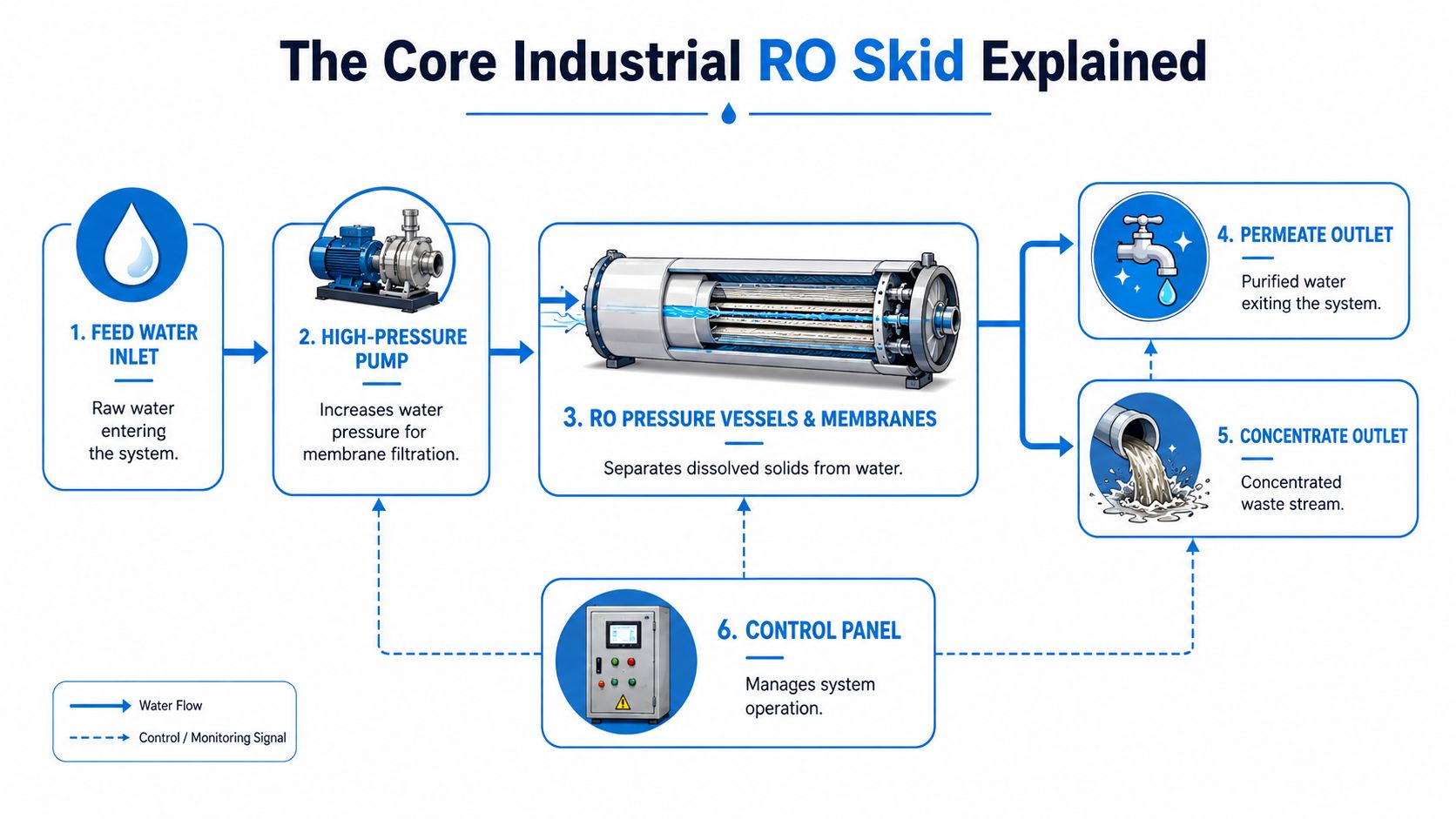
The skid is the center of the process. It contains the pressure-producing equipment, the separation zone, and the control points that determine whether the unit will run steadily or chase alarms. For buyers comparing industrial packages, the skid diagram is where the difference between a commodity frame and a production-grade system becomes obvious.
Here is the core layout you should expect to see:
What belongs on the skid
At minimum, the skid should show feed water inlet, high-pressure pump, RO pressure vessels and membranes, permeate outlet, concentrate outlet, and the control panel. If a supplier can't present those clearly on a reverse osmosis system installation diagram, it's hard to trust the rest of the package.
The pump isn't just there to make pressure. Its material of construction and control strategy have to match the water chemistry and the operating profile. In industrial service, buyers usually look for a pump that can handle continuous duty, stable pressure control, and practical seal maintenance. Pairing that pump with a VFD gives the operator a much cleaner way to control startup and operating pressure than relying on crude throttling alone.
The pressure vessels hold the actual separation assets. This is where membrane selection matters. Buyers often specify Veolia or LG elements because they want a known membrane family with established performance characteristics, supply continuity, and technical support. In process and boiler feed applications, membrane performance is not a soft preference. According to this industrial RO membrane reference, industrial-grade RO membranes are engineered to filter out 95% of dissolved solids and impurities, which is the threshold that makes them suitable for process applications where lower rejection leads to more frequent cleaning and recovery loss.
For teams evaluating membrane platforms, this guide to Veolia ProFlex reverse osmosis systems is a useful buying reference because it connects membrane choice to system configuration rather than treating the element as a standalone part.
How the process streams should behave
A skid diagram should make the three main streams obvious:
| Stream | What it does | What to verify on the diagram |
|---|---|---|
| Feed | Enters the skid and goes to the high-pressure section | Isolation valve, pressure indication, stable inlet conditions |
| Permeate | Leaves as product water | Flow measurement, conductivity monitoring, clean routing |
| Concentrate | Carries rejected solids away from the membrane surface | Backpressure control, reject routing, disposal or recycle path |
Some industrial skids also include a concentrate recycle loop. That can improve hydraulic control in specific designs, but it's only useful when the broader pretreatment and scaling strategy support it. Recycle should never be treated as a shortcut for inadequate feed preparation.
The best skid drawings show operating intent, not just component location.
Control points matter just as much as hardware. Pressure transmitters before and after the high-pressure section, flow transmitters on permeate and concentrate, and quality instruments tied into the control panel give operations a real-time picture of whether the skid is performing to design. Without those signals, the system can still run, but operators won't see fouling, unstable recovery, or product quality drift early enough to act cleanly.
Configuring the Essential Pre-Treatment Train
Most industrial RO failures don't begin at the membrane vessel. They begin upstream, where solids removal, oxidation control, and scaling prevention were either underspecified or arranged in the wrong order. If the pretreatment train is weak, even a well-built skid with premium membranes won't stay efficient for long.
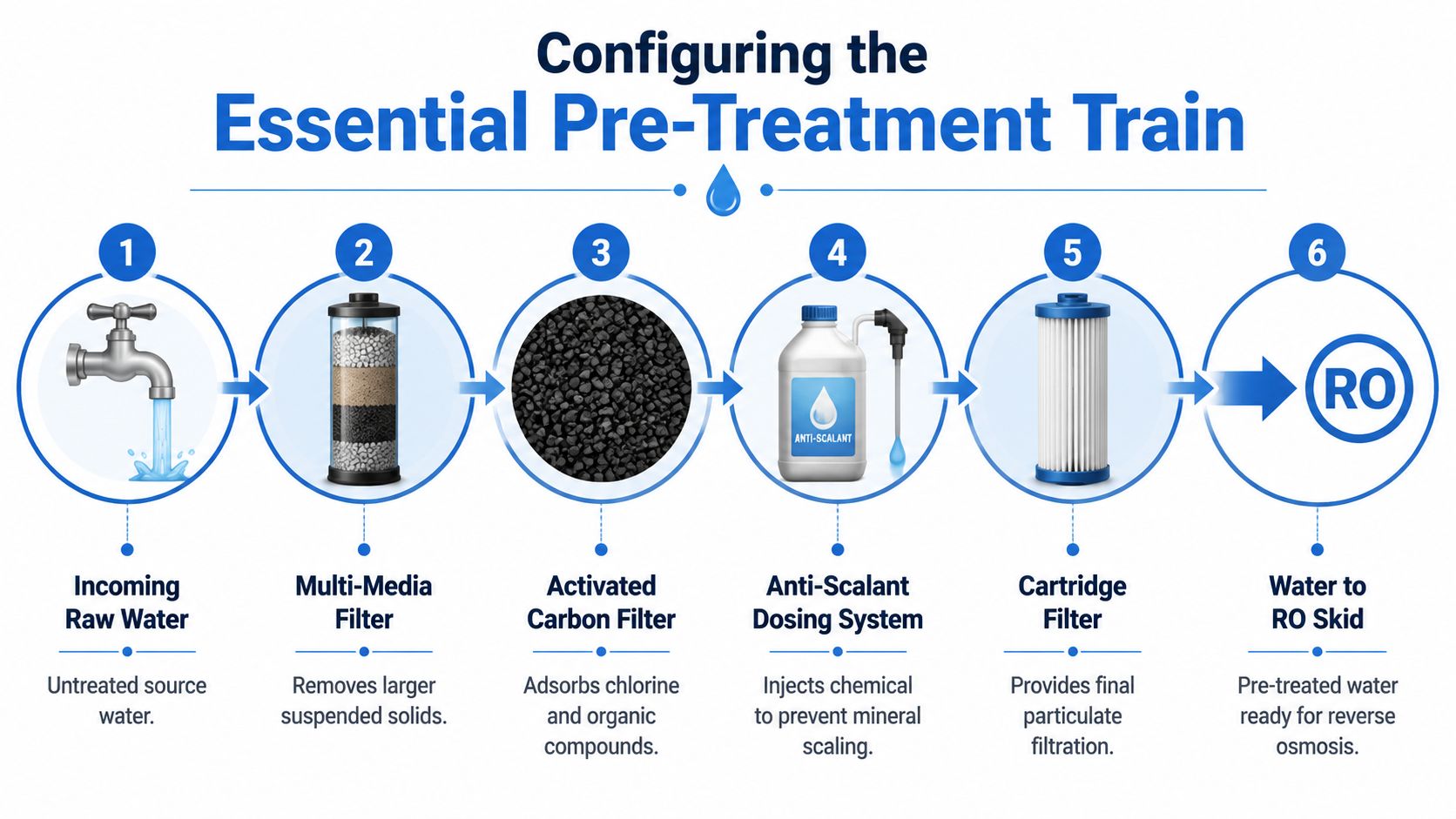
This process flow shows the sequence buyers should expect before water reaches the RO skid:
Why the pretreatment train decides membrane life
Industrial feedwater rarely arrives in a condition that membranes can tolerate directly. Suspended solids, oxidants, hardness, and variable turbidity all create avoidable stress. That's why pretreatment is not optional. It is part of the RO system.
A core rule in industrial water treatment is that the first barrier needs to remove the bulk solids load. According to this industrial RO schematic resource, industrial reverse osmosis systems for process and utility water applications require a multimedia filter as the primary pre-treatment step to remove suspended solids before the RO unit, which directly reduces fouling and extends membrane life in sectors such as Oil and Gas and Mining.
That point is easy to miss when teams focus on the skid first and the feedwater train second. In practice, the opposite approach works better. Start with the raw water analysis, then build the pretreatment sequence that protects the membrane from the actual contaminants present.
A practical equipment sequence
The sequence below works well as a starting framework for many industrial systems, though the exact order and chemistry still depend on the water analysis and operating objective.
- Multimedia filter first: The primary solids barrier handles larger suspended matter before that load reaches fine filtration and membrane surfaces.
- Activated carbon where oxidant removal is required: Carbon has a job. It's there to adsorb chlorine and organics when the feedwater profile demands it. It should not be inserted by habit if it creates unnecessary biological risk or maintenance burden.
- Softener or antiscalant dosing for scaling control: Hardness and scale-forming ions need a deliberate strategy. Some plants prefer softening. Others choose chemical dosing because it integrates better with the process, footprint, or waste profile.
- Final cartridge filtration before the skid: Industrial buyers typically specify a fine polishing barrier, often a nominal cartridge stage such as Fil-trek housings and elements, to keep residual particulate from reaching the high-pressure section.
For packaged filtration buyers, this industrial filtration machine overview is a helpful reference for comparing pretreatment hardware categories before locking in a full train.
A poor sequence usually reveals itself quickly in the field. Differential pressure climbs too fast across cartridge filters. Membrane cleaning intervals tighten. Product quality becomes harder to stabilize. Operators then blame the membrane, even though the underlying issue started in the pretreatment design.
When a project team asks how to improve RO reliability, the answer is usually upstream of the RO skid.
In mining and food processing environments, pretreatment deserves extra scrutiny because raw water conditions can swing during production changes, source blending, or seasonal events. A robust reverse osmosis system installation diagram for industry should therefore show not only the equipment blocks, but also the chemical injection points, isolation valves, and maintenance clearances that let the pretreatment train do its protective job consistently.
Piping Valving and Instrumentation Layout
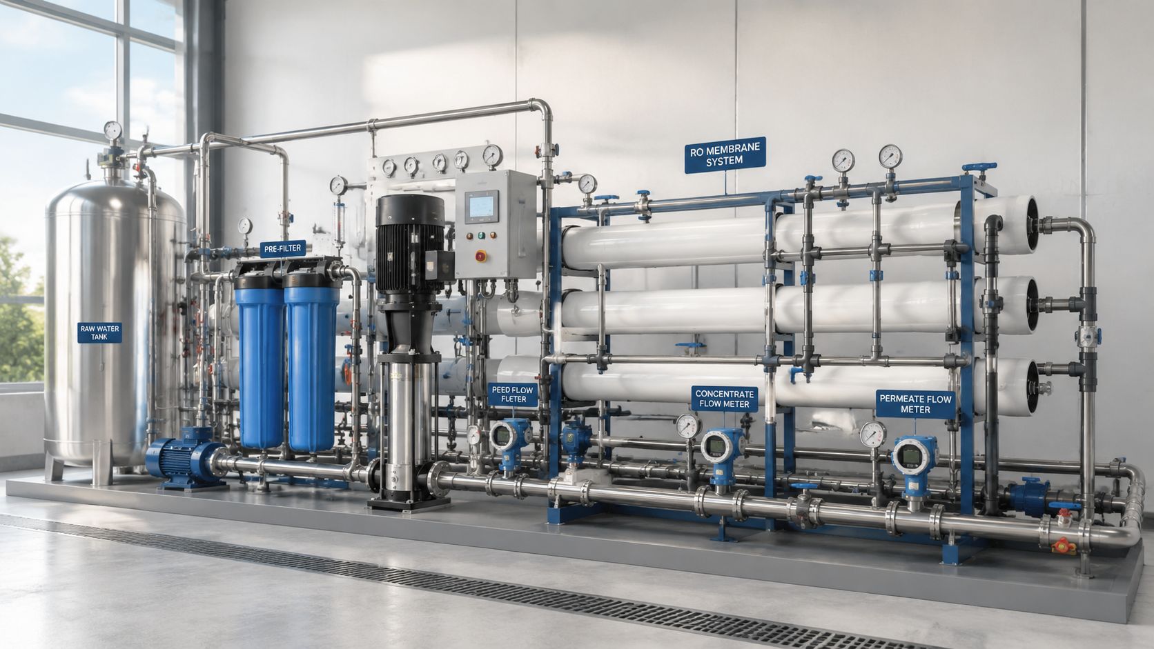
A reverse osmosis system installation diagram becomes useful to operations only when the piping and instrument details are realistic. Industrial systems fail plenty of startup reviews not because the membranes were wrong, but because the valve placement blocks maintenance, the sampling ports are missing, or the instrument taps are installed where they can't produce trustworthy readings.
Choose materials for pressure chemistry and maintenance
Material selection starts with service conditions, not preference. Many industrial projects use Schedule 80 PVC in lower-risk sections because it's economical, available, and easy to modify. Others move to 304 or 316 stainless steel where pressure, temperature, cleaning chemistry, or mechanical durability make plastic a poor long-term choice.
The right answer depends on the exact application. A food and beverage skid may justify stainless for hygiene and plant standards. A mining utility water package may prioritize ruggedness in selected sections and cost control in others. What doesn't work is mixing materials casually without checking pressure class, chemical compatibility, and support spacing.
Use the installation drawing to settle those decisions early. Show reducers, unions, flexible connectors where needed, and support points that stop vibration from transferring into instrument tees and membrane connections.
Lay out valves and instruments for operators not drawings
A functional layout usually includes these items:
- Isolation valves at every serviceable block: Put them around multimedia filters, cartridge housings, chemical dosing assemblies, and the pump train so technicians can service equipment without draining the entire system.
- Check valves in the right places: Use them to prevent backflow through pumps, chemical lines, and sensitive quality monitoring loops.
- Sample ports where quality changes: Place them upstream of RO, on permeate, and on concentrate when troubleshooting requires it.
- Pressure indication across critical restrictions: Gauges or transmitters on both sides of pretreatment filters and around the pump section tell operators where fouling or blockage is building.
- Flow meters on permeate and concentrate: Those readings show whether recovery and hydraulic balance still align with the design basis.
- Conductivity sensors on product water: If permeate quality shifts, operators need to see it immediately, not after downstream complaints.
Here's a simple decision table that helps during design review:
| Layout choice | What works | What usually causes trouble |
|---|---|---|
| Valve placement | Reachable with room to turn and service | Buried behind vessels or mounted too low |
| Instrument taps | Straight runs and readable orientation | Tight elbows, vibration, poor access |
| Sample stations | Located at process decision points | Added only at the final outlet |
| Maintenance clearance | Space to pull cartridges and membranes | Equipment packed tightly against walls |
The drain line detail many industrial drawings miss
Industrial engineers often focus heavily on pressure piping and still under-document the reject and drain side. That's a mistake. The wastewater connection has contamination and code implications, especially where reject lines tie into building drainage.
According to the NAES wastewater air gap guidance, a critical detail is the wastewater line air gap. Codes typically require a 2 to 4 inch vertical gap above the P-trap flood level and a high-point loop in the tubing to prevent back-siphonage. Many commercial diagrams leave that out, even though it's essential for contamination control and code compliance.
Don't treat the reject drain as housekeeping piping. It's part of the sanitary barrier.
For industrial installations, I also recommend checking whether the reject line path creates unnecessary low points, unsupported spans, or difficult cleaning access. A clean drawing is not enough. The route has to survive actual operation, washdown, vibration, and maintenance activity around the skid.
Electrical Controls and System Commissioning
Mechanical installation gets most of the attention, but the control panel and startup sequence decide whether the membranes begin life under controlled conditions or under stress. Industrial RO equipment should never be energized and started like a simple utility pump skid. The control system needs to protect the pump, the membranes, and the downstream process from unstable conditions.
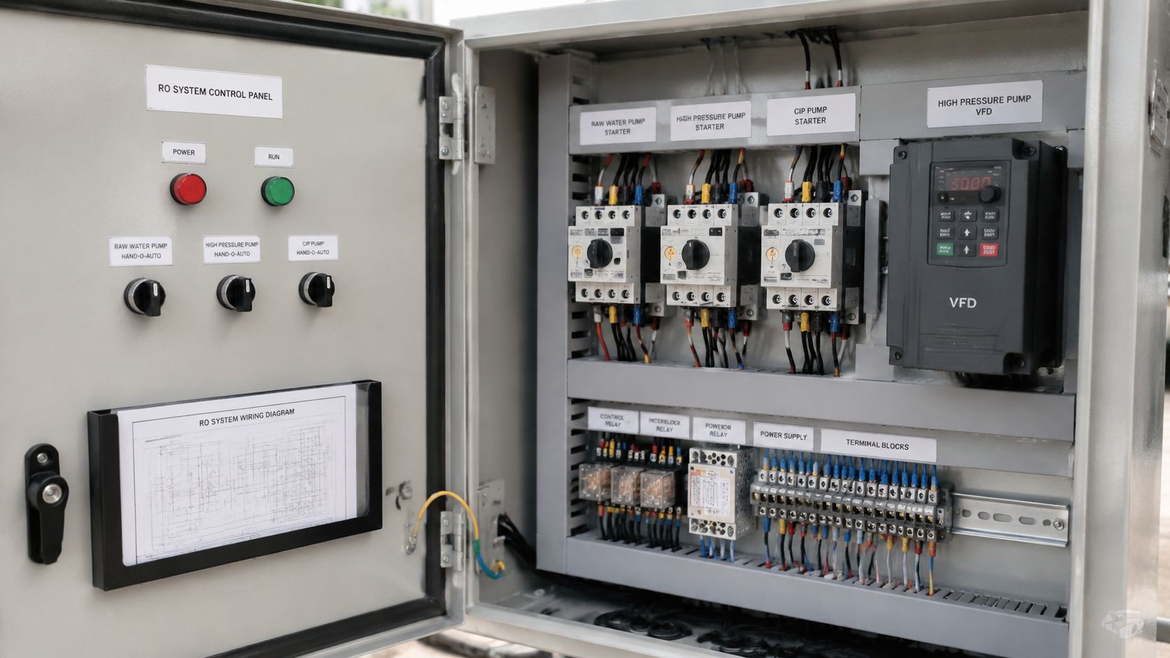
Controls that protect the skid
A strong industrial design usually includes a motor starter, a VFD for the high-pressure pump, and a PLC that processes the main operating inputs. The VFD matters because it allows soft starts and controlled pressure ramping. That reduces hydraulic shock and makes it easier to hold a stable operating point when feed conditions vary.
The PLC should monitor the signals that matter to operators:
- Tank or break tank levels so the system doesn't run dry
- Feed and discharge pressures so the pump and vessels stay inside operating limits
- Differential pressure indicators across pretreatment stages
- Permeate conductivity so product quality is visible in real time
- Flow status on the main process streams
- Alarm states that trigger shutdowns, lockouts, or operator intervention
What doesn't work is overcomplicating the panel with signals that add little value while leaving out the fundamentals. Controls should help the plant make decisions quickly. They shouldn't bury operators in nuisance alarms or force them to infer membrane condition from incomplete data.
Commissioning sequence that prevents avoidable damage
A disciplined startup should move in a fixed order.
First, verify the installation mechanically. Confirm that housings are tightened correctly, the valve lineup matches the startup position, instruments are powered and scaled properly, and all drains and relief paths are open as intended. Check that pretreatment media, chemical dosing systems, and final cartridge stages are ready before the pump is allowed to build pressure.
Next, flush the system to remove fabrication debris and preservatives. New installations often carry fine particulate, handling residue, and packaging debris that should never be forced directly into the membrane array.
Then load the membrane elements correctly. According to the RO installation guidance from H2O Distributors, the RO membrane must be inserted into its housing with the o-ring end first and pushed until fully seated to ensure proper sealing. If it isn't fully seated, the system can suffer permeate contamination and a significant drop in rejection.
A membrane that isn't seated correctly can make a brand-new skid look defective on the first performance test.
After membrane loading, bring the system up gradually. Ramp pressure in a controlled way, verify that permeate and concentrate flows stabilize, and confirm that the control logic is responding correctly to live process data. During this stage, operators should watch for abnormal vibration, erratic flow, trapped air, or quality readings that don't align with the design expectation.
The final check is not whether the skid runs. It's whether it runs predictably. Commissioning is complete only when the operating team can reproduce stable startup, normal production, and safe shutdown using the control logic and the installed instrumentation.
Common Installation Errors and Long-Term Best Practices
A plant can approve a clean P&ID, install premium LG or Veolia elements, and still end up with unstable production in the first year because the field layout ignored service clearances, drain routing, or pretreatment duty. Industrial RO systems fail early more often from integration mistakes than from defective major equipment.
Mistakes that shorten system life
Poor installation geometry is a recurring industrial problem, even without a neat percentage to quote. In tight retrofit rooms, I often see antiscalant lines stretched across walkways, sample tubing kinked behind vessels, and cartridge filter outlets piped with unnecessary high points that trap air. Those details restrict flow, distort instrument readings, and make troubleshooting slower than it should be. On a high-recovery skid, a badly routed impulse line or a concentrate valve installed too close to an elbow can create control instability that operators mistakenly blame on the membrane array.
Undersized or incomplete pretreatment is another expensive error. A skid designed for stable feed will not tolerate raw water swings just because the membrane brand is reputable. If the application is mining, heavy suspended solids and metals loading usually call for more than a nominal cartridge stage. If the application is food and beverage, seasonal hardness and organics can overwhelm a basic setup unless the multimedia filter, softener, carbon stage, or chemical dosing train was sized for actual plant variability instead of average lab water.
Other repeat failures show up during the first maintenance cycle, not the first startup:
- No membrane pull space: End caps can technically be removed, but elements cannot be extracted without shifting adjacent pipework or cable tray.
- Drainage designed as an afterthought: CIP discharge, relief valve outlets, and sample drains end up spilling into the wrong area or backing up because there is no proper air gap and floor drain path.
- Instruments placed where they cannot diagnose fouling: A single pressure gauge on the skid header tells very little. Differential pressure across the multimedia filter, cartridge stage, and RO array matters far more.
- Wrong metallurgy or elastomers for the cleaning regime: Caustic, acid, oxidant exposure, or high chloride conditions will expose weak material choices quickly.
- Pump suction conditions ignored: Inadequate flooded suction, poor NPSH margin, or vibration from bad base alignment reduces pump life and destabilizes feed pressure.
Practices that keep industrial RO stable
Good long-term performance starts with layout discipline. Leave enough clearance to change cartridges, lift membrane elements, remove valve actuators, and calibrate transmitters with tools in hand. If a technician needs to dismantle unrelated equipment to service one component, the installation is not finished properly.
Baseline data should be recorded at handover, under steady feed conditions and confirmed recovery. That baseline should include feed conductivity, SDI or turbidity if available, stage pressure drop, normalized permeate flow, rejection, chemical dose settings, and pump amperage. Those numbers let the operating team distinguish fouling, scaling, pretreatment breakthrough, and mechanical drift before product quality is affected.
Spare parts strategy also matters. Keep cartridge sets, common seal kits, at least one critical transmitter, valve positioner parts, and wear items for the high-pressure pump on site. A structured high-pressure pump maintenance program prevents pressure instability, seal failures, and avoidable membrane stress.
Reliable RO operation comes from correct pretreatment, serviceable layout, stable hydraulics, and disciplined maintenance. Premium components help, but they do not compensate for a poor installation.
A good reverse osmosis system installation diagram should do more than show where pipes connect. It should prove that the skid can be serviced, cleaned, drained, isolated, and operated under real plant conditions without shortcuts. That is the difference between a system that passes commissioning and a system that keeps producing five years later.
Purecowater supports industrial water treatment projects with RO, filtration, EDI, pretreatment equipment, and sourced components from established manufacturers for process and utility water applications. If you're specifying a new system or upgrading an existing train, Purecowater can help your team align equipment selection, integration, and supply strategy with the practicalities of plant operation.